A Photovoltaic Panel connected to the domestic installation (and to the supplier network) produces a direct current (DC) voltage, which is then converted into a synchronized alternating current (AC) voltage by an inverter. This voltage is matched to the same frequency (50 Hz) and a comparable amplitude to that of the grid.
In electricity, current flows if and only if there is a potential difference (ΔV) — particularly in direct current, where only the instantaneous voltage difference determines the current flow. In contrast, in the case of two synchronized alternating sources (same frequency, same waveform), current can flow even if the instantaneous voltages are equal at times, thanks to a phase shift (a few degrees) between the sine waves.
In this context, it is the phase difference between the voltages, as well as the impedance characteristics of the circuit, that determine the existence and direction of the current.
N.B.:
In a 220 V alternating voltage, the voltage varies from +311 V to -311 V. Indeed, the value of 220 V is the effective value (RMS) of the alternating voltage. This is the value used for power calculations and electrical equipment specifications. The alternating voltage oscillates between a maximum positive value and a maximum negative value. The maximum value (amplitude) is actually \( V_{\mathrm{CREST}} = V_{\mathrm{RMS}} \times \sqrt{2} \) → \( 220 \times \sqrt{2} \approx 311\,\text{V} \)
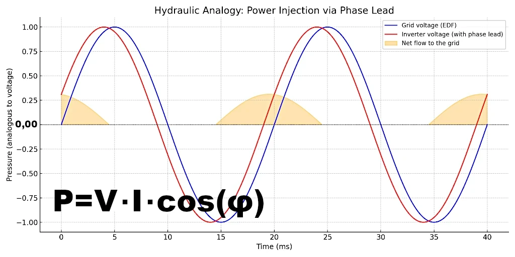
In terms of physics, this transfer obeys the power equation: \( P = V \cdot I \cdot \cos(\varphi) \). This formula is known as the "Active Power Formula in Single-Phase Sinusoidal Alternating Current."
Even if the effective voltage is nominally the same (230 V for example), it is the instantaneous voltage variations (phasing, dynamics, micro-adjustments) that allow the inverter to inject a directed current towards the grid.
Imagine two hydraulic pumps connected to the two ends of the same pipe, each producing a pressure variation at a frequency of 50 Hz.
These variations create pressure waves in the fluid (similar to sound waves) that travel through the pipe. These waves cause areas of compression and relaxation of the fluid, without overall mass displacement, but with local oscillations of water particles.
This system is a good analogy for two alternating voltage sources in an electrical circuit: the pressure represents the voltage, the flow corresponds to the current, and the resistance to flow is similar to electrical impedance.
The two pressures are identical at every moment.
There is no pressure difference between the two ends of the common pipe.
Therefore: zero flow at all times, no fluid movement.
Conclusion: No energy transfer. The fluid is static despite the oscillating pressure.
Opposing pressures: when one pushes, the other pulls.
Maximum pressure difference at every moment.
The fluid oscillates strongly from one pump to the other, alternately.
The flow \( Q(t) \) is in opposite phase with the pressure difference.
The product \( \Delta p(t) \cdot Q(t) \) is negative half the time, positive the other half, but perfectly symmetrical.
Conclusion:
When one pump is at its maximum pressure, the other is at the point of maximum flow (because the pressure gradient is changing).
Pressure and flow are in quadrature (90° shift).
This corresponds to a situation where the instantaneous power is always non-zero, but changes sign during the cycle.
Conclusion:
In this case, the phase shift is neither totally zero (as in the 0° case), nor 90° (where pressure and flow are maximally shifted but without net transfer), nor maximal (as in the 180° case), but intermediate.
The pressure difference is not maximal at all times, but it varies partially.
The flow is also sinusoidal, but it is partially in phase with the pressure.
This phase shift creates a net energy transfer between the pumps, resulting in a real flow of fluid from one pump to the other.
| Case No. | Phase Shift (°) | Pressure Difference | Flow \( Q(t) \) | Instantaneous Power | Average Power |
|---|---|---|---|---|---|
| 1 | 0° | None | None | \( P(t) = 0 \) | 0 (no transfer) |
| 2 | 90° | Maximum | In quadrature with pressure | Sinusoidal, alternating signs | 0 (reciprocal transfer) |
| 3 | 180° | Maximum | Opposed to pressure | Symmetrical sinusoidal | 0 (reciprocal transfer) |
| 4 | Intermediate (e.g., 5°) | Partial but non-zero | Partially in phase with pressure | Sinusoidal, non-zero average value | ≠ 0 (net energy transfer) |
Although an alternating instantaneous flow exists in all cases, a net mass transfer only occurs if the phase shift is partial (different from 0°, 90°, or 180°).
The fluid is therefore the medium of mechanical energy, and can become a vector of material transport in situations of net energy transfer.
 Full text of Einstein's 1905 article on the nature and evolution of light
  The Speed of Light: The Ultimate Limit That Nothing Can Exceed
  Reality Escapes Us: Truths We Can Never Prove
  The Physics of the Universe in 50 Equations: User Guide
  The Kaya Identity: The Equation Complicating Our Decarbonization
  The Unsurpassable Speed in the Universe: When Energy Becomes Infinite
 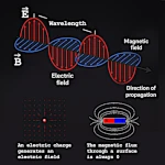 Electromagnetic Runaway: The Secret of the Speed of Light
 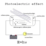 Understanding the Photoelectric Effect: Light and Electrons
 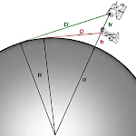 How far is the horizon?
 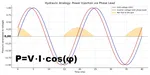 How Do Solar Panels Inject Electricity into the Grid?
  Dynamics of Momentum to explain the propulsion of rockets or jellyfish
 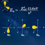 How Electron Energy Dictates Chemical Properties
  The Key Role of Quantum Uncertainty: No Particle Can Be at Rest
  Energy and Power: Don't Confuse Them, Time Makes All the Difference
  Why is there a limit to cold, but not to heat?
  Galileo's Law of Falling Bodies
  The Ideal Gas Law: One Equation, Thousands of Applications
  Schrödinger's Equation Revolutionized Our View of Matter
  The Magic of Noether's Theorem: From the Principle of Least Action to Conservation Laws
  Relationship between gravitational mass and inertial mass and the equivalence principle
  Third Equation of Physics: Momentum to Understand Collisions
  The second essential equation in physics: The intuition of a conserved quantity
  The First Equation of Physics: How to Mathematize Force
  The electromagnetic force or Lorentz force
 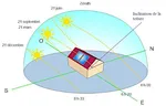 The solar energy received depends on the angle of incidence
  Why is marble colder than wood?
 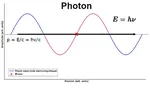 Why does a photon, which has no mass, have energy?
 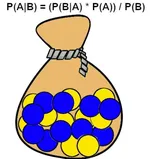 Bayes Formula and Artificial Intelligence
 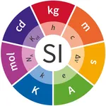 The seven fundamental constants of physics
 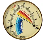 What temperature does it feel like in interstellar space?
 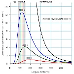 Black body radiation curves: Planck's law
  The equivalence principle, gravitational effects are indistinguishable from acceleration
  E=mc2: The four fundamental concepts of the universe revisited
  How to weigh the sun?
  Equation of the free fall of bodies (1604)
 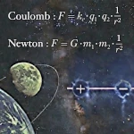 Coulomb vs Newton: The Mysterious Similarity of the Universe's Forces
  Boltzmann's equationon entropy (1877)
  Special relativity equations (1905)
  The equation of general relativity (1915)
  Planetary Rotation Equations: Between Angular Momentum and Gravitational Balance
  Equation of the orbital velocity of a planet
  Planck's equation
  Understanding Schrödinger's Equation Without Math
 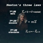 Newton's Three Laws: From the Falling Apple to the Orbiting Planets
  Maxwell's equations
 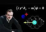 Paul Dirac's equation
 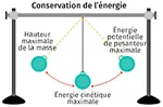 Conservation of energy
  Equation of electromagnetic induction
  Why do elementary particles have no mass?
  Difference between heat and temperature